Pump Drives
The pump drives allow the contemporary running of two or more hydraulic pumps from a single prime mover.
All models can be prepared for various applications:
- basic (B) for independent mounting
- with a overcenter industrial clutch (BD) (BDS)
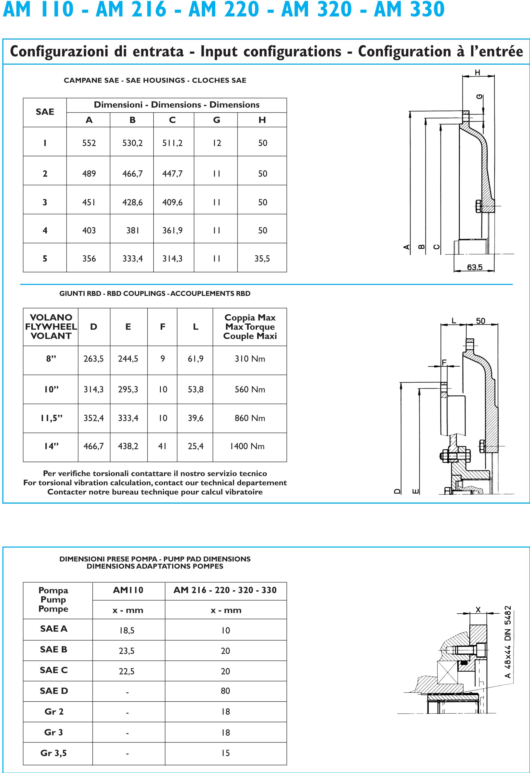
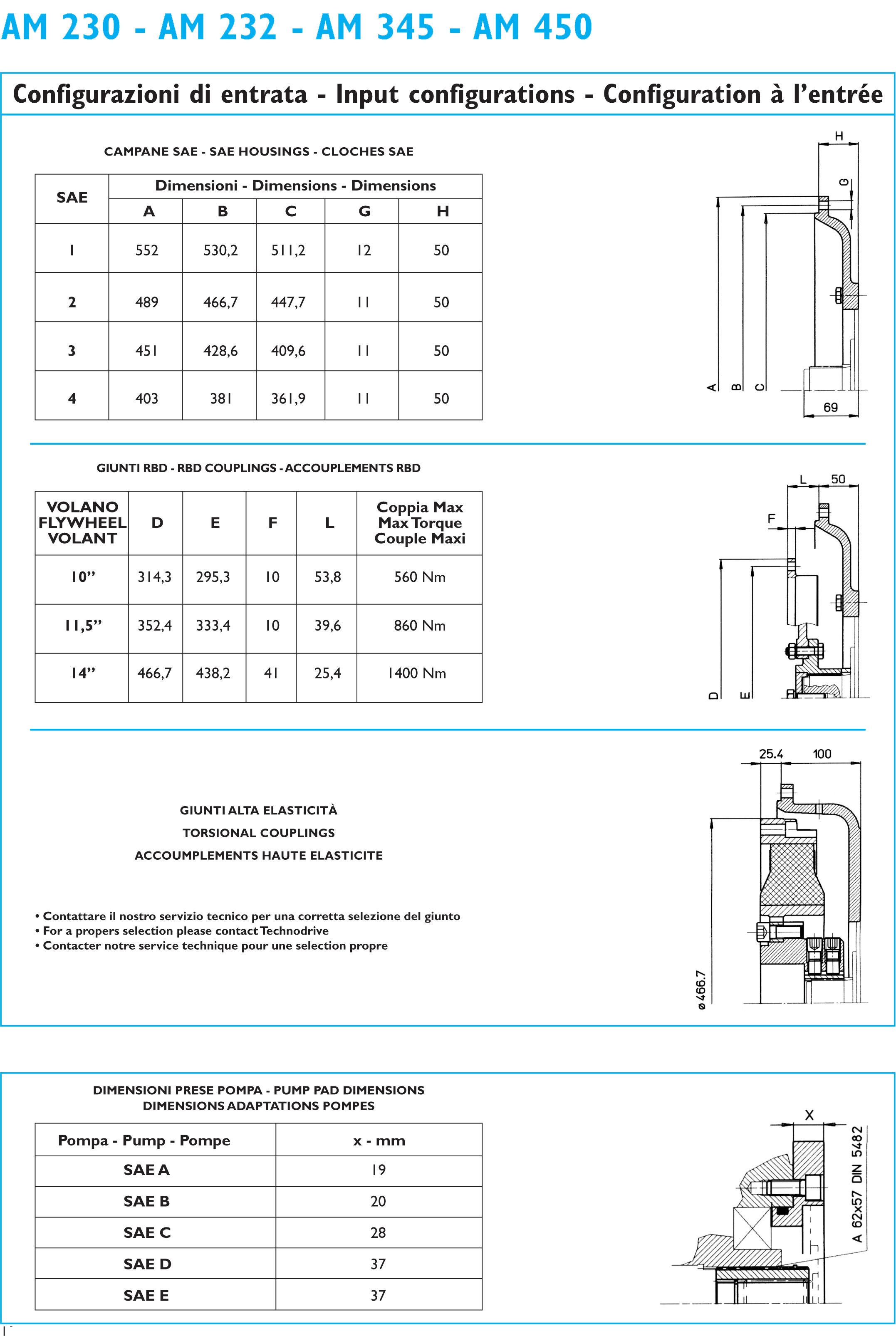
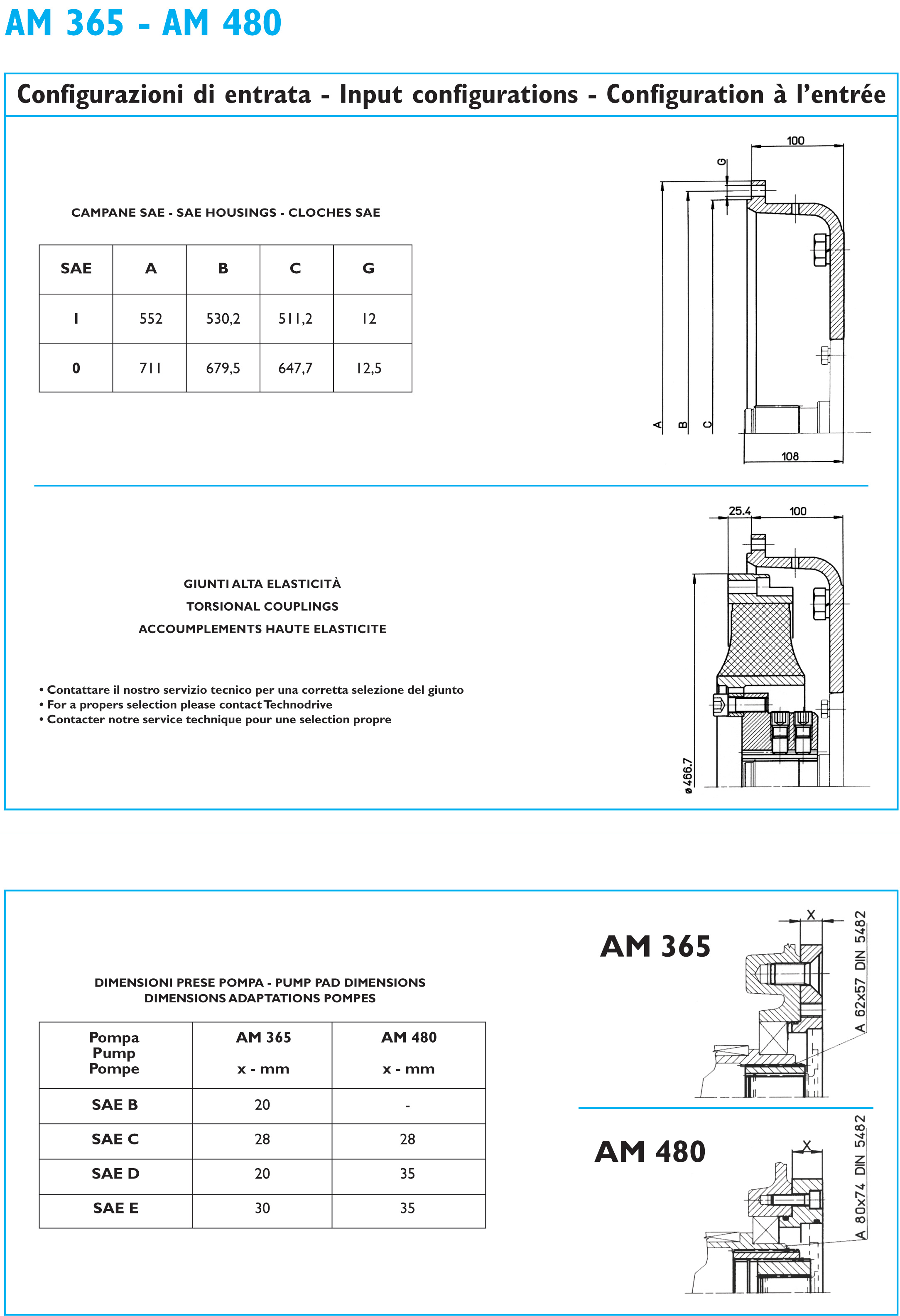
- with housing and coupling connection for diesel engines
Constructively the pump drives consist of:
- cast iron casing
- straight-tooth gears, case hardened – hardened grinded (shaved in series AM 216 – AM 320)
- ball bearings
- shafts in casehardening steel – case hardened – hardened
- Viton seals on input shaft
The kinematic diagram is identical for the various models: the primary gear, which transmits, the drive to the secondary gears on whose axles the pumps are applied, is splined to the input shaft.
The direction of rotation in output is the opposite to the rotation direction in input.
The transmission ratio is identical on ali the outputs (AM 640 may have different ratios on outputs).
SELECTION
The fundamental elements on which the choice of pump drive is based are:
- number and type of hydraulic pumps to be applied
- max torque absorbed by the pump (or by the group of pumps) on each output of the pump drive
- max power entering the pump drive
Depending on the overall dimensions of the pumps, complete with pipes and pipe fittings, it is possible to establish the minimum distance between the pumps themselves. Comparing these values with the values forseen in the catalogue for the output shafts, it is possible to make a choice of type.
Verify that the torque value of each output is kept below the max value shown in the catalogue for the chosen pump drive.
In cases of use in important industrial systems or in marine applications, it is necessary to bear in mind relevant safety factors.
Also verify that the rotation speed of input shaft isn’t more than the max indicated in the catalogue.
In the case of pump drives with clutch BD or BDS verify that the max input torque is at least 20% below the max transmittable from the clutch.
COOLING
Oil working temperature must not exceed 105°C.
Depending on the input power and on duty, a cooling system may be necessary.
It is advisable to check the oil temperature during the first hours of work, making sure that the oil doesn’t exceed 105°C. Ali pump drives, except for AM 216 and AM 320, can be equipped on request with a cooling system consisting of an oil circulating pump mounted on the input shaft, pumps side, an oil/water cooler and relevant pipe fittings.
DIESEL ENGINE CONNECTION
In cases of application to diesel engines, the pump drives can be supplied with housing and coupling suitable far engines with flywheel and flywheel housing dimensions according to SAE standards.
The same dimensions are valid far connections with cluches.
Note: The clutch pilot bearing (to assemble between the flywheel and the clutch shaft) is not included in the supply.
INSTALL
The working position of the pump drive is usually the one shown in the catalogue.
If other positions are requested it is necessary to confer with the technicians at TECHNODRIVE.
Special care must be taken over the fixing of the pump drive.
LUBRICATION
Use gear lube oils with EP additive and minimum viscosity index of 95.
Before use fili to the maximum level mark on dipsfick.
IOil must be replaced after the first 50 working hours. Subsecuent oil changes should be made every 1.000 hours or every 12 months, wichever is the sooner.
Check regularly the oil level.
Oil working temperature must not exceed the 105°C.
INPUT CONFIGURATION


