Power Commander
Features and Benefit
 The Twin Disc POWER COMMANDER® Model EC200 enhanced control system is designed to control the engines and transmissions of a boat or ship, while providing the propulsion with shift a throttle logic to improve overall operation and convenience.
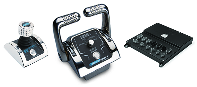
A SINGLE LEVER controls throttle and ahead-neutral-astern selection so operation is effortless. Docking is simplified!
MULTI-FUNCTION SELECTOR lets you select idle speeds for docking and maneuvering, synchronized engine operation, or trolling operation with two-speed selections.
A STATION SELECT SWITCH with individual LED indicator for port and starboard system lets you confirm that the controllers are ready for your command. Neutral start logic in the EC200 control provides protection against start-in-gear conditions.
UP TO 6 CONTROL STATIONS are easily provided for by adding optional station doublers. All controls provide for direct connection of 3 stations, and doublers can be used on any of the three station inputs. Custom configurations can provide for more than 6 stations.
3 PRESET IDLE SPEEDS let you select an idle speed for docking and maneuvering under various conditions or for just loafing along. This feature permits “jogging” into gear at higher idle speeds when docking.
OPTIONAL ENGINE SYNCHRONIZATION electronically matches engine speeds of two or more engines as long as the control head levers are kept within 7 degrees of each other and synchronization is switched on. The control head lever handles are designed to operate jointly with one hand. Because synchronization mode operates with the control levers approximately in the same position, abrupt changes of engine speed are avoided when entering and leaving synchronization mode.
OPTIONAL TROLLING VALVE CONTROL lets you operate your trolling valve from the same control lever by converting the lever motion from throttle position command to trolling position command. Trolling mode and one of two preset engine speeds are selected at the same time via the multi-function selector. Allowing lever position for entry and exit from trolling mode is limited to a few degrees around forward and reverse detent to protect the propulsion system components.
OPTIONAL SHAFT BRAKE CONTROL can synchronize the application of a shaft brake automatically. Shaft brake application times are selectable and proportional to the throttle lever and time at that level. The design allows for faster gear changing without damage to the propulsion system or stalling of the engine.
OPTIONAL PRESSURE SWITCH input controlled throttle clamp is available for positive control of engine throttle on high horsepower transmissions which may exhibit more variability in engagement times. This feature will prevent damage to clutch plates and annoying engagement jars caused by engine speed-up prior to closure of the clutch.
MECHANICAL OVERRIDE “COME HOME” FEATURE is provided by a clutch in each actuator. In the event of a power failure, mechanical type throttle and gear selector can be operated manually without modification or disassembly of any components.
OPTIONAL ELECTRONIC INTERFACES for engine throttle, gear selectors, and trolling valves are available for all popular brands of equipment. All engine interface circuitry is is isolated to prevent interaction between the engine controller and the EC200 control system. Direct, proportional, and three valve neutral impulse style drivers are available for gear selector. PWM drivers are available in either open loop or current feedback configuration for control of trolling valves.
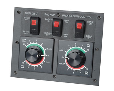
OPTIONAL EMERGENCY BACKUP system is available for “fully electronic ” EC200 controlled propulsion systems and include a separate control head, wiring system, and power input from an emergency source.
SIMPLIFIED INSTALLATION is assured by fully connectored components and pre-connectored cables. System component connector sizes are arranged to minimize installation errors and preparation time. No hydraulic or pneumatic hoses, pumps or valves to plumb, drain, or leak test. Mechanical actuator directions for throttle, troll, and gear are selectable by programming shunts conveniently located in a topside access panel. Synchronization gain, hold in gear or shaft brake times, and elevated idle level adjustments are also available via the access panel. Insulated mounting holes in the control enclosure eliminate the need for isolating sub bases when mounting controls. Rugged, heavy gauge stainless steel control enclosures withstand hostile installations and operating stresses.
Enviromental Specifications
The EC200 control system is designed to meet or exceed the following specifications. These specifications are selected to satisfy US, Australian, and European regulatory agency requirements and recommendations.
TEMPERATURE RANGE
Operating: 0 to 70 degrees Celsius ambient
Storage: -20 to 85 degrees Celsius ambient
MOISTURE LEVEL
Relative humidity from 0 to 100%
Splash and spray up to 15 PSI on all normally exposed surfaces and 5 PSI on all surfaces which are normally inside or protected from weather and waves
VIBRATION LEVEL
8 g’s, 3 planes, 0.15 displacement, 5 to 45 Hz., 1 million cycles
ELECTRICAL BONDING
The bonding circuitry design of the EC200 control system allows it to work in either U.S. (ABYC) battery negative to control enclosure wiring, or European/Australian totally isolated battery negative wiring, with control enclosure tied to hull plate or not connected at all.
EMI/RFI SUSCEPTIBILITY LEVEL
150 volts per meter for control head and associated cable
100 volts per meter for entire system, from 10 kilohertz to 10 gigahertz
System Specifications
OPERATING VOLTAGE
12 volt system – (“A” suffix) 10 volts to 16 volts operation, 9 volts cranking
24 volt system – (“B” suffix) 20 volts to 32 volts operation, 18 volts cranking
CURRENT REQUIREMENTS
12 volt system – 15 amps peak (2 seconds per command change), 1 amp nominal
24 volt system – 8 amps peak (2 seconds per command change), 0.8 amps nominal
Note: The above current requirements are based on control systems that have actuators for both throttle and gear. If the system has electronic options that reduces the number of electro-mechanical actuators that are used, the current requirements will be reduced significantly.
ENCLOSURE MATERIAL
A012 Aluminium Bronze with chrome plating or gold-tone coating for control head.
304, passivated stainless steel for control enclosure, bottom, and cover plates.
EXPOSED SURFACES STABILITY
Resistant to normally encountered levels of dust, dirt, oil, greese, solvents, gasoline, diesel fuel, hydraulic fluid, and sea water.
MECHANICAL ACTUATOR
90 inch pounds torque at 26.4/13.2 volts system power input
60 inch pounds torque at 20/10.0 volts system power input
1.0 seconds maximum Neutral to Gear with full torque load, at 26.4/13.2 volts system power input
100 milliseconds minimum clutch holdover during power interruption
10 inch pounds torque maximun drag from disengaged actuator (power off)
CIRCUIT BREAKER RATING
8 amps medium fast trip breaker capable of interrupting 50 amps repetitively
4 seconds nominal trip time for 16 amps, 0.6 seconds nominal trip time for 25 amps
IGNITION INPUT
1.4 watt maximum inductive load for power from same level as main control power
10 milliseconds nominal drop-out time for loss of power
START INTERLOCK RELAY
5 amp inductive load rating sufficient for most starter relays and some solenoid coils. Isolated relays contacts have non-polar MOV protection.
OPTIONAL SOLENOID OUTPUTS
3 amp direct drive from system power connected to the EC200 control for gear, troll, or shaft brake outputs.
Direct drive outputs have transient suppression diodes which are referenced to battery negative power.
OPTIONAL SYNCHRONIZER ENGINE SPEED INPUTS
0.5 volts RMS sensitivity for magnetic pickups or tach generators
300 volts impulse and oscillation filtering with optional ignition interface module
OPTIONAL PRESSURE SWITCH INPUT
Ground true input sourcing 10 milliamps from internal pull-up when option is selected.
Technical Information
 SYSTEM DESCRIPTION
The basic Model EC200 Control System consists of a control, a lever assembly and one or more wiring harnesses. The control system coordinates the transmission direction and the engine RPM. Various accessories and options are available to interface the EC200 system to expand configurations and provide performance enhancements appropriate to today’s technologically intense yachts, performance boats, work boats, and ferry boats.
CONTROL
One control is required for each engine. If the control uses mechanical actuators, there are rotary devices with electrical clutches which disengage when power is turned off, allowing manual operation of transmission direction selector and the throttle, without the need to dismantle components of the control system. A separate connector is provided for each of the three station control head cables, the optional speed sensor cables, a communication cable, and one multi-purpose cable for power, troll, and options. The stainless steel control housing includes isolated mounting feet, a topside access panel for setup, and cable clamp brackets for mounting mechanical push-pull cables to interface to throttle governors and transmission selector levers.
LEVER ASSEMBLY
Throttle lever and transmission direction selections are combined into the lever motion. A multi-function rotary selector provides for idle lever selection, and activation of troll or synchronization options when available in the system. A guarded station select push-button and individual station selected indicators are provided for command and identification of station in control. The station select push-button is also used to enter the direction override by holding down while leaving neutral. Neutral indicators are also provided and are controlled by circuitry which monitors the gear command and the output of the control. Neutral indicators will blink when in neutral gear condition is a result of a direction override.
TROLL CONTROL
Trolling valves can be controlled mechanically or electronically. In systems that have mechanically positioned governors and transmission selectors, it may be necessary to use a separate external troll actuator. In systems with electronic engines or solenoid shift options, a troll actuator may be included in the main control enclosure and eliminate the need for additional wiring and mounting.
PHANTOM CONTROLS
Operation of systems with three to five engines can be simplified by the use of Phantom Controls to duplicate gear and throttle commands to inward and center propulsion units. Single, dual, and triple Phantoms allow full operation of the boat’s propulsion from one dual lever control head when Phantoms are enabled, and separate levers or combinations when Phantoms are disabled.